Summing Mixer Setup – Documentation – Additional Options – Components
Analog Studio Mixer Docs, Schematic, Wiring Diagram & Monitor Controller Layout
Explore example blueprints and design layouts for custom analog studio mixers and monitor controllers. This section includes detailed schematics, wiring diagrams, and configuration references to help you understand routing options, summing architecture, and component integration in real-world setups.
Table of Contents
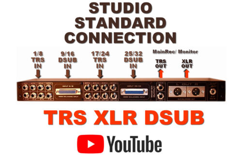
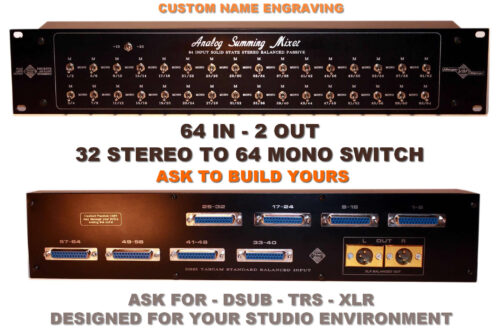
Connection – Stereo Balanced Studio Standard Connectors
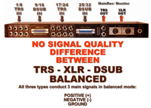
There is NO Signal Quality difference between TRS, DSUB, and XLR.
All three types conduct 3 signals in balanced mode:
- POSITIVE (+)
- NEGATIVE (-)
- GROUND
Connecrion type:
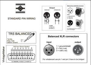
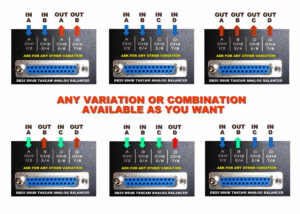
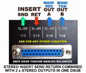
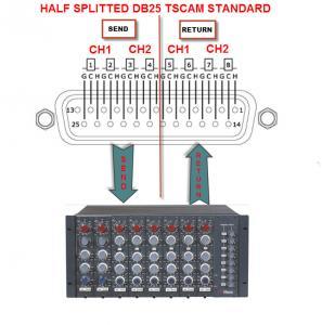
- D-Sub DB25 Tascam Standard Analog Balanced
- TRS 1/4″ balanced: Tip=hot (+), Ring=cold (-), Sleeve=GND
- XLR balanced: 1=GND, 2=hot (+), 3=cold (-)
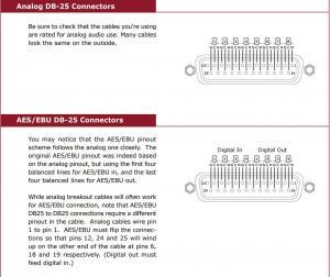
DSUB – DB25 Tascam Analog Standard
Make sure you’re using Analog DB-25 – NOT (AES/EBU digital)! AES/EBU pinout scheme follows the analog one closely.
The original AES/EBU pinout was indeed based on the analog pinout, but it uses the first four balanced lines for AES/EBU in and the last four balanced lines for AES/EBU out. Always use a compatible cable with the standard Analog Tascam. Download Tascam pinouts pdf
Setup Configuration with Example and Visuals
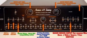
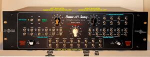
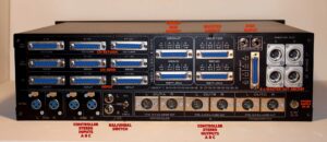
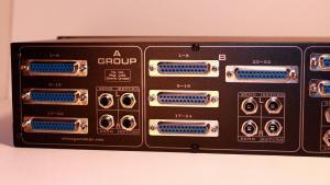
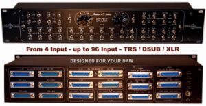
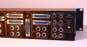
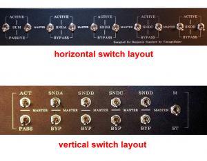
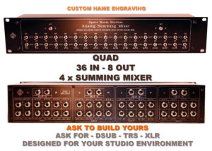
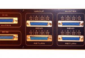
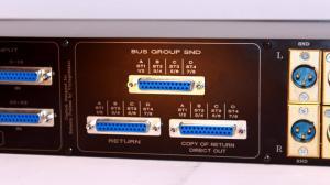
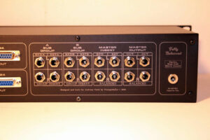
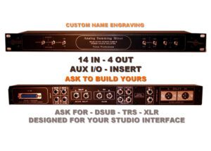
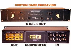
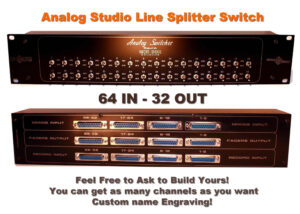
The following images show diverse possibilities of custom builds. You can actively participate in the planning, essentially designing it yourself, or ask for my help to create the best unique custom studio gear for you.
Input Channel Count and type
- 1U Rack:
- DSUB: up to 40-48 ch input
- TRS: up to 32 ch input
- XLR: 8 ch input
- 2U Rack:
- DSUB: up to 96 ch input
- TRS: up to 64 ch input
- XLR: up to 16 ch input
- 3U Rack:
- DSUB: up to 128 ch input
- TRS: up to 96 ch input
- XLR: up to 32 ch input
Output channel Count and Type
- 1U Rack:
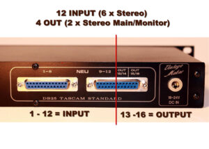
- DSUB: Up to 16 channels out (8 stereo) or ask for custom pinout
- TRS: Up to 8 channels out (4 stereo)
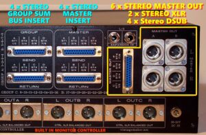
- XLR: Up to 6 channels out (3 stereo)
- In the case of a 16-channel input through DSUB input.
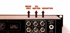
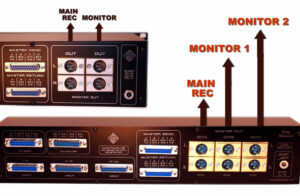
The recommended output count is 4 ch / 2 x Stereo: Main Rec | Monitor. This allows real-time monitoring of the master output.
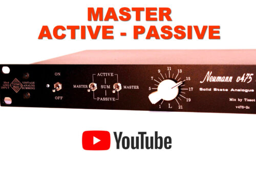
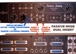
Master Active Passive – Dual Solid State Switch
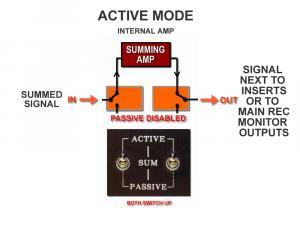
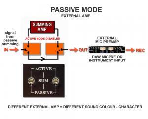
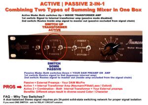
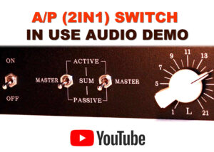
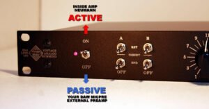
The Active/Passive selector switch lets you choose between the internal transformer amp (Active mode) or an external amp (Passive mode), giving you a wide tonal analog versatility. You can use external preamps, combine them with the internal transformer, or use the internal transformer alone to create different sound colors. This provides flexibility to shape your sound and add your own unique tonal character.
Possible Combinations – Variations for Different Sound Color and Character:
- Passive: External Preamps (Your Preamps)
- Active 1: Internal Transformer Amp (Neumann, Filtek, Lawo)
- Active 2: Combined – Internal Transformer Amp + Your DAW or External Preamps
Benefits: Different amplifiers provide unique sound color and character.
- Passive = Non-powered
- Active = Powered
Possible combinations offer different sound colors and characters: Passive uses your own external preamps, Active 1 features an internal transformer amp (Neumann, Filtek, Lawo), and Active 2 combines the internal transformer amp with your DAW or external preamps. Each combination provides a unique sound, allowing for greater flexibility in your mixes.
FAQ – Why Two Switches Instead of One?
The reason for using two switches instead of one is:
- Durability & Quality – A high-quality solid-state switch that can handle 24 signals at once is difficult to find and not cost-effective.
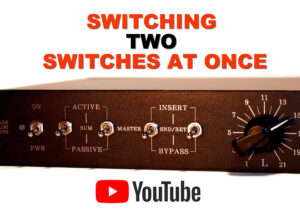
- Signal Handling – To manage 24 signals, we use two 12-pin stereo switches (as shown in the videos, where you can easily switch both simultaneously).
- Clean & Isolated Signal Flow – The dual-switch design ensures that the dual-balanced stereo signal remains clean and isolated from input to output.
- Alternative Option – If you prefer a single-switch solution, check out the “Power ON Activated – Relay” option (see below).
Master Active Passive – One Switch Relay
Power Modes & Relay Control
- Active Mode: POWER ON
- Passive Mode: POWER OFF
- Relay Control: Power-On Voltage-Controlled Relay Circuit
This setup ensures seamless switching between active and passive modes while maintaining signal integrity.
Mono Input Conversion Switch versions
The Mono Channel Conversion Switch allows you to control how stereo or mono signals are handled in your mix:
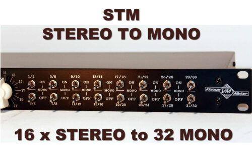
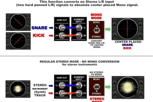
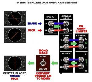
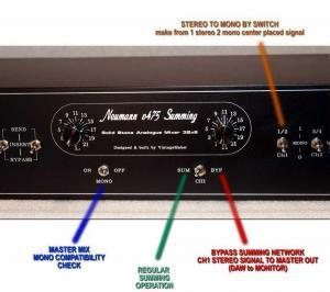
- STM (ONE) Switch: Stereo to Mono Switch Combines a stereo (L/R) input into two identical Mono Center Placed signals.
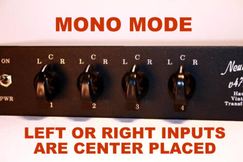
- Per Channel Mono Switch: Lets you choose whether an individual left or right input should be centered (mono) or stay hard-panned.
- LCR Switch: A 3-way (Left Center Right) switch to pan audio left, center, or right.
With the Mono Channel Conversion Switch, you can:
- Keep a stereo signal (as is) hard-panned (L/R Stereo Input) Panning from the DAW (Stereo Synth / any other Stereos
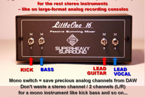
- Convert it to mono and center the sound. If 2 mono instruments (e.g., kick/bass) are sent to the summing inputs, you can leave them on the L or R side, or switch to center to have the sound centered and heard equally in both speakers.so it’s centered and evenly heard in both speakers.
It gives you flexibility in how you position sounds in your mix.
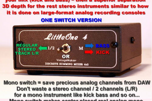
- Why Mono Switch?
- Simply because it gives you the Big Analog Console like Mono Sounding!
- Ultra-Precise Center Placed Mono: Provides extra stable, real analog mono base on Kick, Bass, Main Vox, and Snare.
- Separation for Stereos: Offers superior separation and 3D depth for the rest of your Stereo Instruments.
- Save channels: You don’t have to waste precious analog channels in your DAW by using two channels (L/R) for a mono instrument.
Important: The Mono Input Conversion switch is for Mono, Single-channel instruments like Mono kick / bass – NOT FOR STEREO L/R – TWO Channel Instruments.
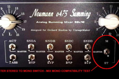
*there’s another switch called the Master Stereo To Mono switch, which is for Mix – Mono Compatibility Test
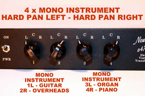
Hard panning Left (L) or Right (R) means that an audio signal is sent entirely to one side of the stereo field—either the left or right speaker—without any signal in the opposite channel.
With the Mono Channel Conversion Switch, you can:
- Keep a signal hard-panned (fully left or right) for a wide stereo image.
- Convert it to mono so it’s centered and evenly heard in both speakers.
This is useful for precise stereo placement, avoiding phase issues, and ensuring clarity in your mix
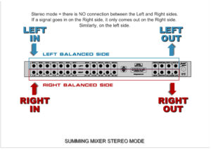
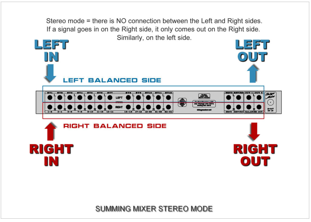
Principles: The summing mixer has TWO separate, independent sides:
- LEFT SIDE: Left input goes to theLeft output.
- RIGHT SIDE: Right input goes to the Right output.
- Additional inputs follow a similar pattern for a comprehensive stereo mix.
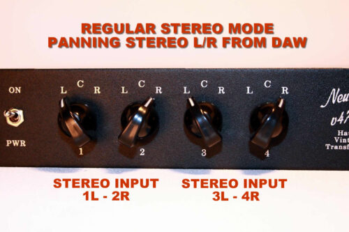
- STEREO – Stereo Instruments – regularly – Panning From DAW
Mono instruments: in the DAW sequencer (Steinberg cubase, pro tools, flstudio, reaper, logic pro, Ableton etc.) should place the kick hard left, the bass hard on the right, and so on.
Stereo instruments: Connect the summing mixer according to the analog outputs of the DAW; If you don’t use mono channels in your mix, simply turn down all the mono switches, and you’ll have a fully stereo analog summing mixer with panning control available from the DAW.
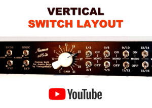
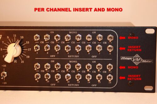
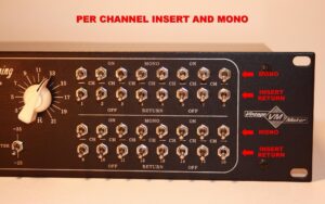
1x MONO – Per Channel Switches
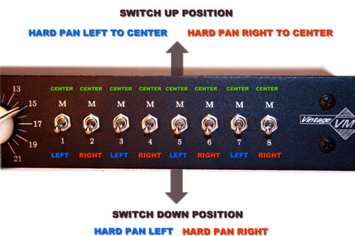
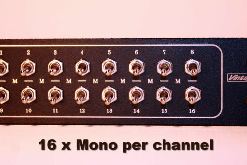
- Each Input Channel has its own Hard pan Left / Hard Pan Right Input – To Center – Mono Switch
- Convert “SEPARATELY” choosing L or R input (Hard Panned Left / OR / Hard Panned Right) input signals to become Center placed – or leave hard panned L / or / R (see benefits and example below in blue).
- By the Per Channel Mono Switch you can choose to convert ‘SEPARATELY’ by selecting either the hard-panned Left or hard-panned Right input signals to the center position, or you can leave them as hard-panned L or R (stereo).
1x STEREO (2 In) TO 2 MONO – STM Switch
STM Switch turns L/R inputs ‘COMBINED’ (two hard-panned L/R inputs) into an absolutely centered mono signal (1 x stereo to 2 mono). For example, ‘SNARE’ on channel 1 (left), ‘KICK’ on channel 2 (right).
LCR Hard Pan Left – Right – Center Mono Rotary Switch
PAN option with 3-position rotary switch between hard panning Left, Center, or Hard panning right, giving you complete control over the spatial placement of individual audio sources.
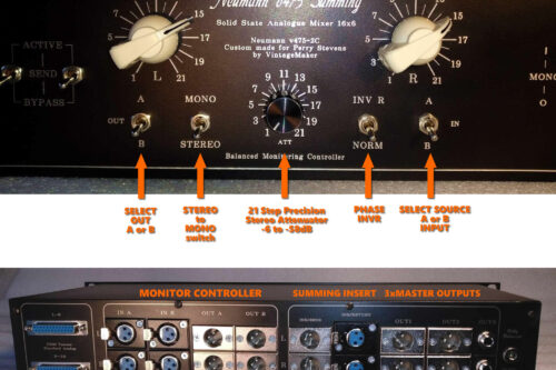
Master Out Mono Mix Switch
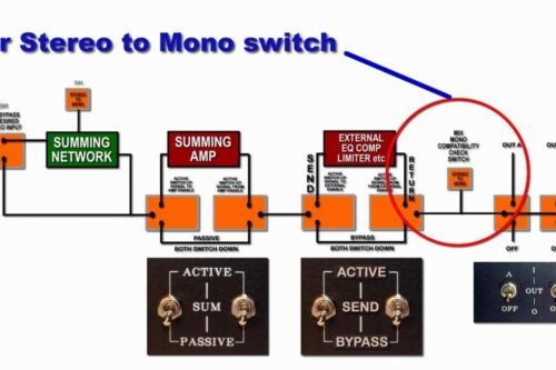
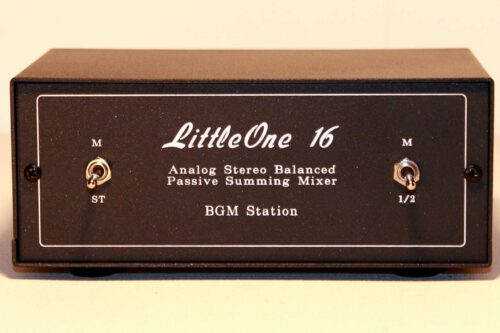
Mono Mix Compatibility Test switch
Sometimes just because a mix sounds good in stereo doesn’t mean it will sound good when the left and right channels are combined into a mono signal. In some cases, you may hear what is known as comb-filtering, which will color the sound of your mix and cause peaks and dips in its frequency response. In some cases, instruments may lose their integrity or even seem to completely disappear from the mix
- Placed before Inserts or Master Outputs
- Checking your mix for Mono compatibility as you go is a good preventative measure
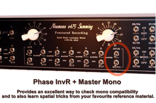
Phase Invert – InvR – switch
Phase InvR – Invert Right side of the stereo signal
First, what is phase inversion?
Inverting a wave’s phase means swapping the location of its peaks and troughs. This creates cancellation when peaks of one wave coincide with the troughs of the other wave. Phase inversion is a subtle, yet versatile music production tool capable of many distinguished feats.
Phase Invert R + Master Mono mode
Reversing the phase of the right channel and mono-ing it with the left and sending the result to both speakers is particularly useful for assessing the width content of your mix and distortion characteristic by effectively replacing the ‘centre image’ with the out-of-phase information.
Passive Mode Insert
Passive Mode has its own dedicated insert. (see Master Active/Passive section)
This function allows you to insert any external preamp into the signal chain in Passive Mode before the Master Insert (for example, an external Tube amp or other color amp). With the Active/Passive switches, you can instantly switch between the internal amp (Neumann, Filtek/Lawo) and your external preamps.
This gives you a lot of freedom to bring various external transformer or tube amp sounds into the recording chain, allowing you to combine the effects of different processors in the sound of your mixes.
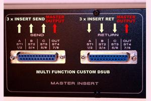
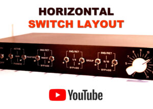
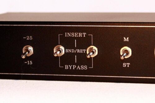
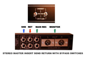
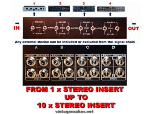
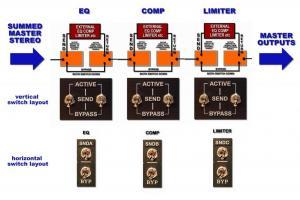
Master Insert Send Return Switch
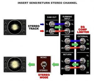
Allows you to INSERT SEND or BYPASS the master stereo L/R signal to external processors like EQ, Comp, Limiter, and then RETURN it to the master out (print/record).
- Allows switching between processed and unprocessed signals for comparison purposes.
- Master SND/RET is placed before the master out.
- 100% of the signal is routed to SEND.
- 1st Switch: enables sending to external (routes the master to SND).
- 2nd Switch: enables the return from external (routes the return to the master out)
FAQ – Why Two switches instead of One?
- Simply because it’s hard to find a solid-state switch that can handle 24 signals at once in terms of cost-effectiveness.
- To handle 24 signals we need 2 X 12 pin Stereo switches (see videos you can easy switch 2xSW at once)
- The dual switch keeps the dual balanced stereo signal flow clean and isolated from input to output.
- If you only need one switch, check the ‘Power ON Activated – Relay’ option. (see bellow)
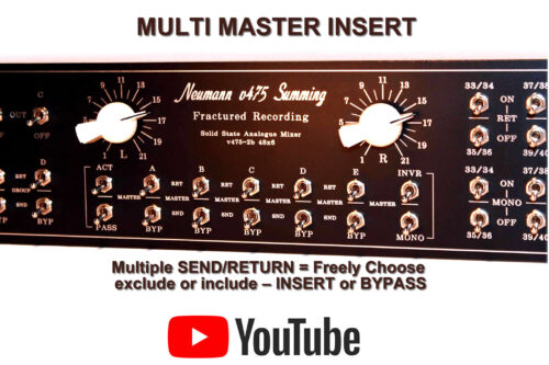
Multi Master Insert Send Return chain
Multiple SEND/RETURN = Freely Choose – exclude or include – INSERT or BYPASS (either one or more) external gear in the chain.

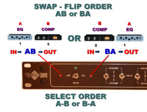
Insert Swap Sequence Order Switch
FLIP OR SWAP – ACTIVATE OR BYPASS – YOUR ANALOG PATCHES INSTANTLY
The order of the outboards can be swapped in any other variation (let me know)
- AB / or BA
- BC / or CB
- CD / or DC
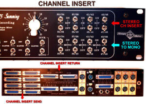
Channel Insert Send Return
The input is linked to the send output, which goes to your external processor. The return signal is controlled by the Insert Bypass switch:
- If the switch is OFF (down position = disabled), the signal goes straight to the summing bus — no external processing.
- If the switch is ON (up position = enabled), the processed signal from your external gear returns and is sent to the summing bus.
- The input signal is always present on the corresponding send out (stereo channel)
- The Return bypass switch enables or disables the return function:
- Bypass switch OFF (switch down): Input → Sum Bus → Master out (regular summing operation)
- Bypass switch ON (switch up): Input → Send → External Process → Return → Sum Bus → Master out
- The Mono switch converts the processed signal to mono after it returns.
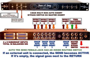
Auto TRS – Master Insert – Send – Return
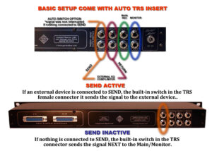
Automatically switches audio channels to SEND out when the jack plug is inserted.
Operation:
- TRS JACK PLUGGED IN = SEND ACTIVE
- TRS JACK UNPLUGGED = NO SEND = Signal next to Master outputs
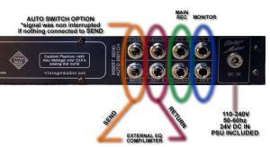
Master Insert Send AUTO TRS: no front-side switch; the TRS SEND connector female-jack has an inside routing switch – (check the listing image). When an external unit is connected, SEND becomes active; if empty, the signal goes to the RETURN and Master outputs. The RETURN serves as an additional output when the Send is empty.
AUTO INSERT TRS CONNECTOR OPERATION
- AUTO INSERT SEND TRS ACTIVE :If an external device is connected to SEND, the built-in switch in the TRS female connector sends the signal to the external device.
- AUTO INSERT SEND TRS INACTIVE: If nothing is connected to SEND, the built-in switch in the TRS connector sends the signal next to the Return and Main/Monitor
Key Points:
- The signal remains uninterrupted if nothing is connected to SEND.
- When the plug is inserted, the internal switch activates insertion detection
Operation Continuation:
- The signal remains uninterrupted if nothing is connected to SEND.
- As soon as you connect any audio signal to the SEND OUTPUTS, the main signal (before master outputs) gets interrupted. It is then processed through an external device and is brought back to the summing mixer via the RETURN INPUTS, whether it is an INSERT or a SEND FX.
- The amount of SEND FX signal (like the amount of reverb) then depends on the DRY/WET signal of the SEND FX device.
Auto TRS Multi Bus Insert Send Return – combined with bypass master insert
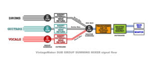
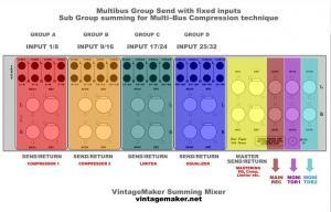
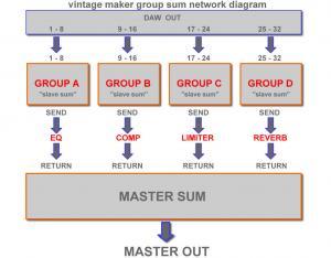
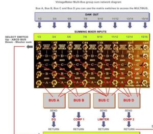
MultiBus SubGroup MixBus
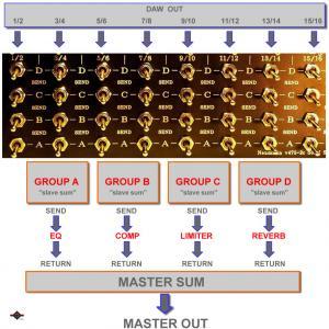
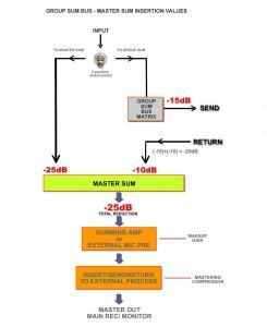
Sub Group summing for Multi–Bus Compression technique. Fixed sub-mixers (Group SUM ABCD) with dedicated inputs; each sub-mixer (slave sum) group comes with individual send/return for external processing, then returns to the Master SUM for final analog summing.
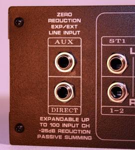
Expansion – Expander AUX Input
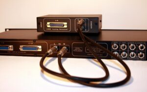
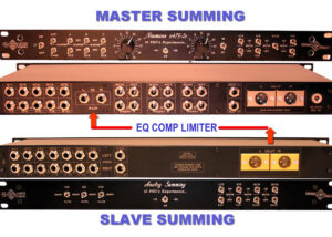
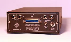
Allows linking of another (secondary slave) Passive or Active summing unit or any standard line input source.
1. Scenario:
Passes a line-level input signal without any reduction directly into the summing circuit. This way, the AUX input becomes part of the summing circuit network.
This is typically used when connecting another (slave) passive or active summing unit to expand your summing setup.
2. Scenario:
Acts as a single-signal colorization path when routed through the internal transformer amp (if present), enabling analog harmonic enhancement and sound coloration (if internal transformer present)
In this case, all other regular summing inputs should be muted or disconnected, so that only the AUX input remains active and valid.
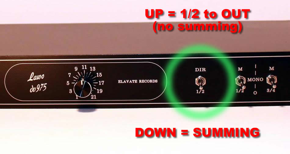
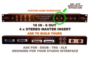
DIR (direct) Input to Output switch – Partial Bypass – 1 Switch Version
There are two versions of the bypass summing option:
- Partial Bypass – 1 Switch Version
This means that a given input (e.g., 1/2 in) either goes to the summing or directly to the output, but the other summing channels remain active. These channels need to be muted in the DAW. - Full Bypass – 2 Switch Version
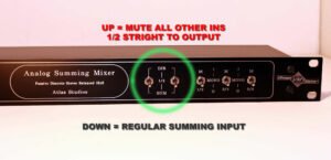
Similar to the previous version, but here all other summing channels are completely muted by a second switch. Only the selected channel goes to the output when both switches are activated (switched up).
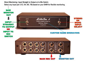
Partial Bypass – 1 Switch Version – Direct Monitoring: Input Straight to Output or to Mix Switch
The DIR Input Switch enables direct monitoring from your DAW interface by routing the input either to the summing mixer or directly to the master outputs. No need to unplug monitor cables—keep your interface connected to the summing mixer at all times. Direct Monitoring – Input to Output – ot Input to Mix – switch. You don’t have to unplug your interface monitor in everyday work; you can keep it connected at all times to the summing mixer.
- Down Position: Input signal is routed to the summing mixer for analog mixing (standard summing operation).
- Up Position: Input signal is sent directly to the master outputs at full volume.
Important:
- Other summing channels remain active—mute them in your DAW.
- Power off the internal amplifier to prevent speaker damage.
- Set the summing mixer to passive mode (if currently active).
- When using active mode for the first time, operate with low-level DAW signals.
- Configure your DAW monitor outputs for either instrument output or main mix monitor output—refer to your DAW’s mixer routing settings.
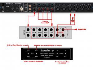
UAD Apollo Twin, x6 x8 x8p example:
You don’t have to unplug: In “everyday” work, UAD monitor out is routed directly to the summing mixer (pre-production, programming, editing, etc.). Switch Monitor OUT to DIRECT OUT mode, and you’ll have straight monitoring from the Apollo interface through the summing mixer.
At the same time, you can use the monitor input/output as an instrument input for the summing mixer, allowing you to send more valuable analog channels to the analog mixer to achieve a more detailed, deep, and wide-resolution sound.
- Monitor Switch DOWN: Normal mode – Use Apollo’s monitor outputs for general tasks (e.g., assign instrument tracks).
- Monitor Switch UP (OUT): Direct mode – Apollo’s monitor outputs are sent straight to the summing mixer 2 x Stereo master outputs.
*Summing 1-8 inputs are still active (mute from DAW).
*Equivalent signal on both stereo outputs.
Benefits:
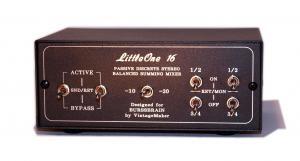
You have 2 stereo outputs on the LittleOne Summing Mixer. The signal is the same on both outputs: one stereo output goes to the Apollo Unison preamps to record the material, while the other goes directly to your monitors. This allows you to record exactly what you hear, latency-free (without analog-to-digital conversion latency).
DIR (Direct) Input to Output or Mixer Switch:
- Down Position: Standard summing mixer input with resistor attenuation for analog mixing.
- Up Position: Bypasses summing mode input by sending the 7/8 input signal directly to the master outputs (no summing attenuation). This allows you to route your DAW interface’s monitor out signal straight through the direct input to output. You can choose to have the 7/8 (or another input) placed before the attenuator (if present) or sent directly to the two stereo outputs.
Simply put, if you’re using the Summing mixer in monitoring (direct out) mode instead of summing mixer mode, you don’t need to unplug anything. Just switch the DIR input to OUT mode, and your DAW interface’s monitor output will be routed to the summing mixer outputs.
Keep your interface monitor connected at all times—no need to unplug during daily use!
DIR (direct) Input + Bypass Summing Switch – Full Bypass – 2 Switch Version
Full Bypass – 2 Switch Version – Direct Input switch + Bypass Summing Switch (2xSwithes)
This dual-switch function mutes all other summing inputs, keeping only the DIR INPUT active.
Don’t hassle with unplugging DAW Main Outputs during everyday work
- Keep only DAW Main Outputs active and mute the rest inputs.
- Down Position: Corresponds to the regular summing mixer input (analog mixing). DIR+BYP is inactive.
- Up Position: Mute all inputs, allowing only DAW Main Outputs (1/2 or other) to go straight to the Master Outputs without any reduction in signal volume, as it is sent from the DAW Main Outputs.
- DIR+OUT/BYP DOWN POSITION = REGULAR SUMMING INPUT
DIR+OUT/BYP UPPER POSITION = STRAIGHT TO OUT (NO REDUCTION)
*All other summing inputs BYPASSED – MUTED - Switch 1: Route the desired stereo input to Master out
Switch 2: Mute/Bypass and exclude the other summing inputs
You can freely select any channel 1/2, 7/8, 14/15, and so on… - Important note! Power off the internal amp to avoid speaker damage!
Set Summing to Passive mode (if it is active).
In Active mode (first time use), operate with low-level DAW signals!
Example:
- Main Out L/R = DAW Monitor Out
- 1/2, 3/4, 5/6, 7/8 = DAW Line Outputs
Scenario 1: Use all 10 outputs for analog summing purposes. You can configure Main Out (DAW Monitor Out) to be assigned to a stereo track from the DAW mix (please test it out). Adding the remaining 8 outputs results in a total of 10 analog outs from the DAW. When the DIR+Bypass switches are in the down position, regular summing operation occurs, and all 10 inputs go to the summing circuit. The main rule is that the more analog channels, the higher the analog resolution.
Scenario 2: When the DIR+Bypass switches are in the up position, only the Main Out L/R (DAW Monitor Out) goes straight to the main outputs, and the remaining 8 inputs are muted. Mute all inputs, allowing only DAW Main Out L/R to go directly to the Master Outputs without any reduction in signal volume, as it is sent from the DAW to the summing input. In everyday work, there’s no need to unplug your interface monitor (out); you can keep it connected at all times to the summing mixer.
Direct Output (Input copy)
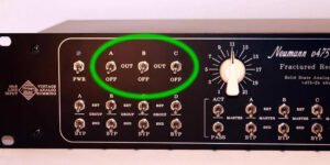
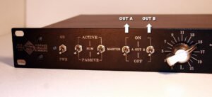
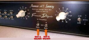
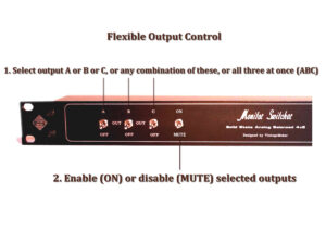
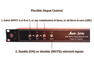
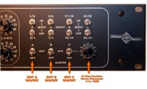
Master Out – ON/OFF – (MUTE)
By this option you can enable (ON) or disable (OFF) Mute master outputs
- Master Out A (on/off) – MUTE
- Master Out B (on/off) – MUTE
- Master Out C (on/off) – MUTE
SELECT I/O Routing – switch
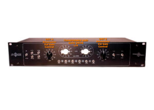
Variable Headroom Gain Switch
The Variable Headroom Gain Switch offers a broad range of gain and volume settings suitable for various applications and gain stages.
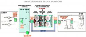
Variable Headroom Gain Switch: It provides a wide gain-volume range for different applications, offers gain stages between various microphone preamps or DAW interface inputs, and accommodates various source inputs, such as synthesizers or DAWs. Placed after passive SUM BUS (passive mixer) determines main out (total) gain reduction – for different (pre amps) applications – gain stage – volume range. With different gain reductions determine what sounds better for your mix
- 1. Whether it’s with fewer input signals and more amplification.
- 2. Or the other way around, with more signals and less amplification.
- Benefits: You can overdrive the summing inputs with different gains to achieve more saturation and warm harmonics.
Available 2-position switch values (select yours)
- -6dB/-16dB
- -10dB/-20dB
- -15dB/-25dB
- -20dB/-30dB
- -25dB/-35dB
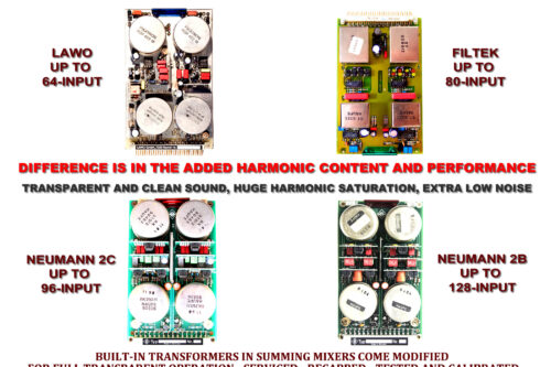
TRANSFORMER TYPES: NEUMANN – FILTEK – LAWO
Please note: All Vintage Transformer Amps are Transparent and Clean.
BUILT-IN TRANSFORMERS IN SUMMING MIXERS COME MODIFIED FOR FULL TRANSPARENT OPERATION, SERVICED, RECAPPED, TESTED, AND CALIBRATED!
The difference is in the added harmonic content and performance.
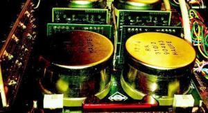
- Neumann V457: Two Haufe Output transformers: Positioned as an entry-level option, it features relatively good harmonic content and effective noise isolation. Capable of handling up to 16 channel inputs.
- Lawo DV975: Equipped with Four 2-in 2-out Pikatron Transformers, it imparts an SSL-like sound, showcasing solid harmonic content and effective noise isolation. Capable of accommodating up to 64 channel inputs.
- Filtek DV1175: Outfitted with Four 2-in 2-out Haufe Transformers, it provides good harmonic content and effective noise isolation. Additionally, it comes equipped with Neumann-Haufe Transformers (called Neumann-Follower) Capable of handling up to 80 channel inputs.
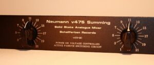
- Neumann 2C: Four 2-in 2-out Haufe Transformers, it offers huge harmonic content and excellent Signal-to-Noise Ratio (SNR). Capable of accommodating up to 96 channel inputs.
- Neumann 2B: Four 2-in 2-out Haufe Transformers, it delivers extra huge harmonic content along with excellent noise isolation and SNR, making it a rare and legendary option. Capable of handling up to 128 channel inputs.
- Please Note
- NO COMPROMISE ALL-STYLE PURPOSE AUDIO TRANSFORMERS
- GENUINE NOS TRANSFORMER AMP FROM LARGE VINTAGE GERMAN MASTERING CONSOLE
- MODIFIED FOR FULL TRANSPARENT OPERATION, SERVICED, RECAPPED, TESTED, AND CALIBRATED
Audio demo comparison test ITB vs OTB digital vs analoque see more….
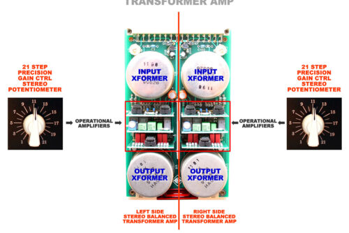
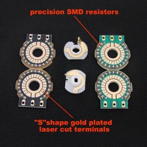
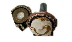
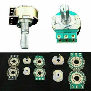
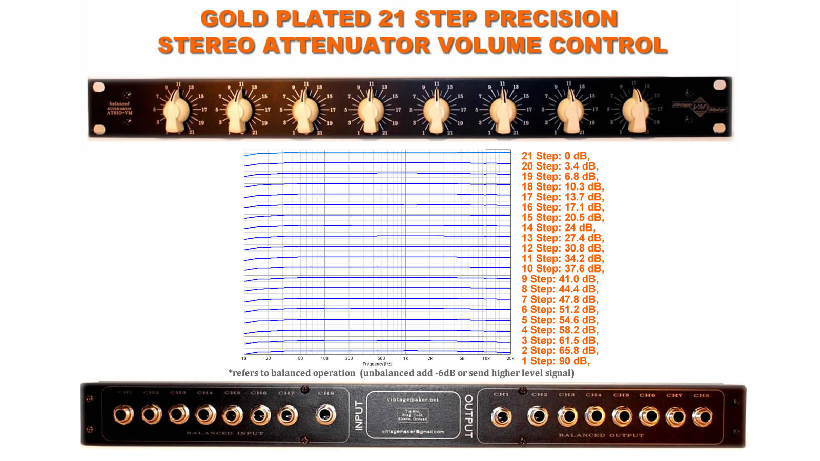
21-Step Precision gain control – Neumann
- Number of steps: 21
- Gold-plated signal path
- Extremely short signal path
- Channel matching: +/-0.1 dB
- Polished ‘S’ shape wiper and contact pins
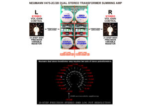
FAQ: Why are there 2 (L/R) pots on Neumann?
- Simply because Neumann is a dual stereo amp (2x Stereo amplifiers).
- The Neumann 2C/2B electronic circuit requires 2 x stereo potentiometers per side.
- It’s easy to set both the Left and Right side gains equally with 2 x 21-step precision potentiometers.
21-Step Precision Vol control – Monitor Controller
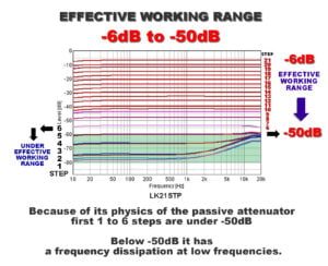
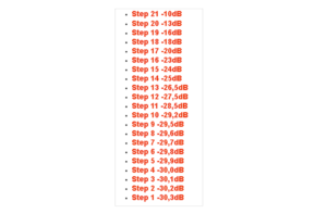
Precision attenuator Effective work range -6dB to -50dB
The first five steps experience dissipation due to the nature of the passive attenuator physics.
21-Step Precision Vol control – ONE STEREO POT Passive Summing Out
- Attenuator (+) – 0 to -25dB divided into 21 steps.
- Example: Summing Base reduction of -10dB (+) -20dB attenuator range.
- The adjustable range can be fine-tuned from -20 to -30dB using the attenuator.
21-Step Precision Vol control – Mono Input I/O
21-Step Precision Vol control – Mono Input -or- Output Trim Pot Attenuator / Per Side
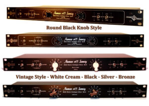
Knob Style and Color
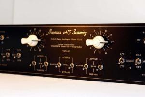
- Vintage-style White “chicken head” knob
- Vintage-style Black “chicken head” knob
- Vintage-style Silver “chicken head” knob
- Vintage-style Bronze “chicken head” knob
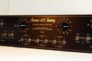
- Round Black – solid aluminum-shaped knob
Built-In Integrated Monitor Control Inside the Summing Mixer
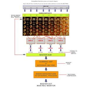
Multi-bus – Matrix – Summing Mixer
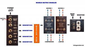
The matrix allows you to send a single channel to multiple outputs (A, B, C, D) in any combination (like A+B, A+C, A+B+D). This lets you send the same signal to different external processors, enhancing focus on a specific channel or instrument.
ABCD BUS matrix switch for MULTI-BUSS compression/external routing processes. (Limited availability)
STEREO TO MONO conversion switch available only after RETURN / before /signal enter to master summing network *Mono CHANNEL conversion available on fixed group multibus only It’s a special unique developed mixing and routing system.
Separate instruments into different categories that will allow freedom of movement. (source MICHAEL BRAUER PRODUCTIONS)
- A – Instruments that are in the upper midrange of a song, such as vocals or keyboards, synths, percussion. Bring up the vocal a lot and it will only effect the instruments assigned to A Choose instruments for a buss that will compliment each other.
- B – Instruments that anchor the song such as drums, bass, maybe cello, congas. Adding more bass or kick will only have an effect on the other instruments assigned to B. Choose instruments that will compliment each other.
- C – Instruments that create transient midrange power and will have a lot of rides, such as guitars.
- D – Instruments that need the warmth of tube and are not played staccato. To be used in combination with other categories for glue factor.
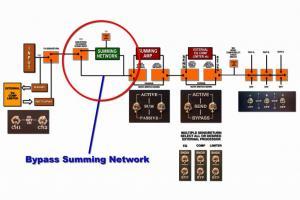
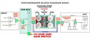
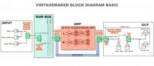
Block Diagram
PSU – Worldwide – 110V-to 240V – External Power Supply
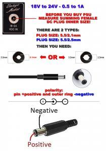
Neumann, Lawo, and Filtek transformer summing amps are equipped with an INTERNAL voltage regulator-filter and stabilizer circuit. The provided compact external power supply, a Switching PSU, ensures a stable 18 – 24VDC, eliminating the need for an additional one. Please do not use a foreign PSU!
The power supply comes with an EU plug. Buy a cheap EU to US/UK/AU travel plug adaptor at your local store!
PSU Details:
- Input: 110-240VAC
- Output: 18-24VDC, 0.6-1.5A (worldwide)
- Plug Type: EU plug
Box Sizes
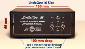
- 1U 19-Inch Rack, Passive, DEPTH: 110mm (4.33 inches)
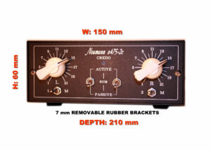
- 1U 19-Inch Rack, Active, DEPTH: 180mm (7.09 inches)
- 2U 19-Inch Rack, Passive, DEPTH: 180mm (7.09 inches)
- 2U 19-Inch Rack, Active, DEPTH: 180mm (7.09 inches)
Specs
- Max Input Level > +26dBu
- THD+N < 0.005% • IMD < 0.005% Frequency Response: Flat within 0.1dB from 10Hz -30kHz Crosstalk rejection: > 98dBu @ 1KHz
- Signal-to-Noise Ratio (SNR): -110dB
- Noise at Unity Gain: 20Hz to 20KHz: < -89dBu
- Noise at Nominal Mix: 20Hz to 20KHz: < -92dBu
- Input Impedance: 600 Ohms – 25K Ohms Balanced
- Output Impedance: 40 Ohms -1K ohms Balanced
- Frequency Response: Flat within 0.1dB from 10Hz -30kHz
- Sum Bus Input Reduction: -6dB -10dB -15dB / -20dB / -25dB (customizable)
- Variable Switch Reduction: -6dB -10dB -15dB / -20dB / -25dB (customizable)
Analog studio mixer with detailed documentation, schematic, and wiring diagram layout. Features a multibus compression matrix, summing mixer channels, master insert, group send/return, mono sum bus, phase control, AUX expansion, stereo stepped level controls, and attenuators. Supports TRS, XLR, and DB25 (D-Sub) connections
Of course! Here’s an extended version of the components overview without any links, focusing purely on the hardware elements:
Component Overview
VintageMaker summing mixers and monitor controllers are built using premium-grade, studio-proven components to ensure exceptional sound quality and long-term reliability. Each element is carefully selected to serve professional analog workflows with precision and flexibility.
Core Components Include:
- Neumann-Haufe, Filtek, and Lawo Transformers – Legendary audio transformers known for their musical saturation, transparency, and vintage analog character.
- 21-Step Precision Attenuators – Stepped gain controls for exact stereo balance and repeatable settings, ideal for mastering and critical mixing tasks.
- High-Quality TRS, XLR, and DB25 (D-Sub) Connectors – Fully balanced connections for clean signal transmission and seamless integration with studio gear.
- Stereo-to-Mono (STM) Switches – Convert stereo channels to mono with a dedicated switch for precise summing and mono compatibility checks.
- Master Insert Points (INSA/INSB) – Dual balanced TRS insert chains for routing outboard compressors, EQs, or other processors.
- Phase Invert Switches – Instantly invert phase on selected channels for proper phase alignment and correction.
- Full Bypass and Direct Out Options – Bypass summing for A/B comparisons or direct routing to outputs without summing coloration.
- Active/Passive Mode Switching – Choose between transformer-based passive summing or discrete active summing circuits depending on the tonal character desired.
- Mono Sum Bus and Aux Expansion Inputs – Send mono signals independently or expand your setup with additional AUX inputs for slave summing units or line-level signals.
- Noise-Free Analog Summing Circuitry – Custom discrete designs engineered for ultra-low noise and wide dynamic range.
These components come together to create a versatile, modular, and high-headroom analog summing solution tailored for hybrid and analog mixing environments.

