


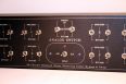
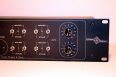
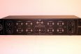
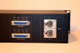


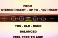



8 x Stereo Mastering Insert Bypass & Flip-Swap – I/O Precision Attenuator
Price range: 1.150.00 € through 1.245.00 €
ANY CONNECTOR TYPE CAN BE ORDERED IN ANY SEQUENCE AND VARIATION
SELECT ALL OPTIONS!
8 x Stereo Mastering Insert Bypass & Flip-Swap Relay Studio Outboard Switcher – I/O Precision Attenuator
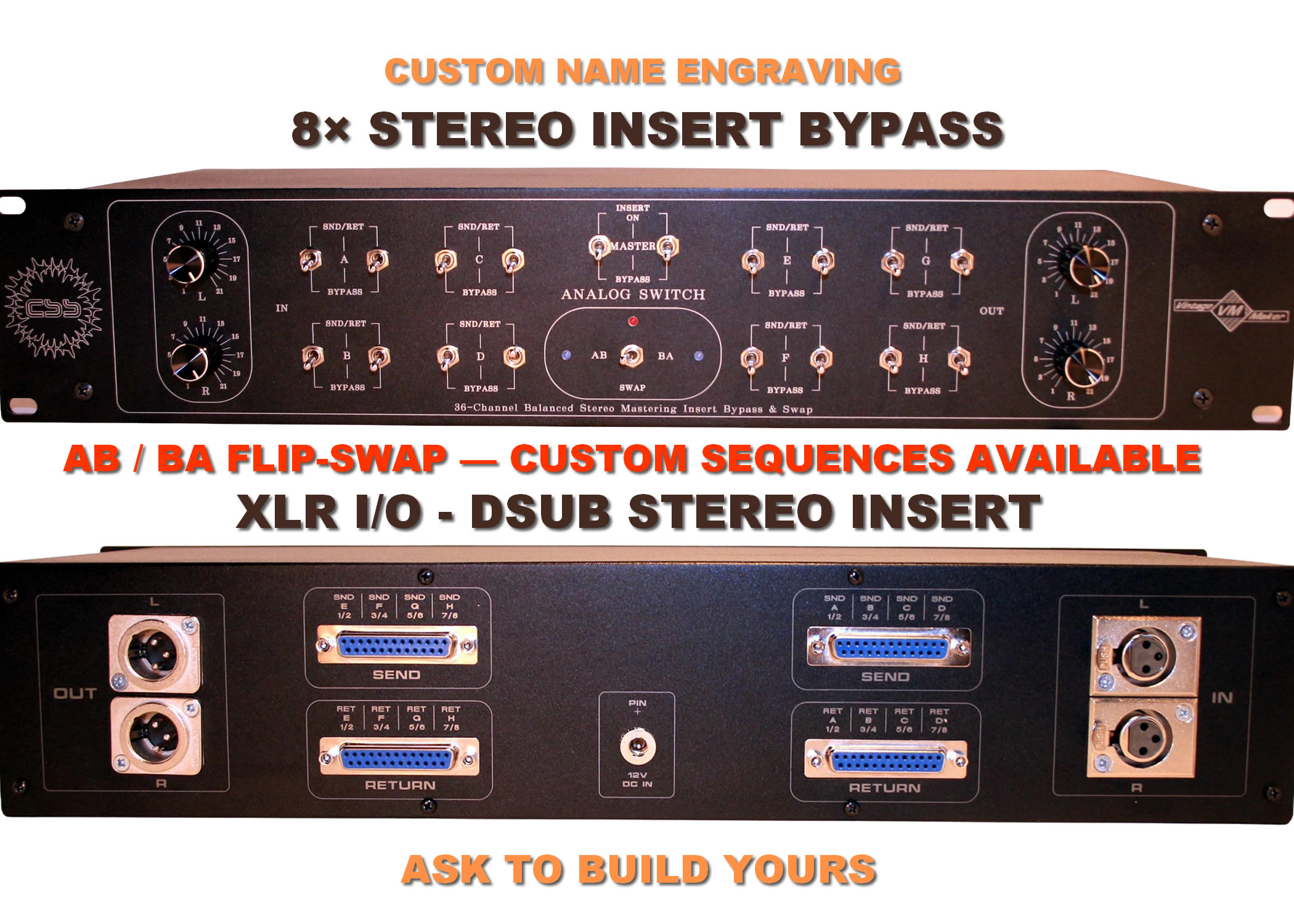
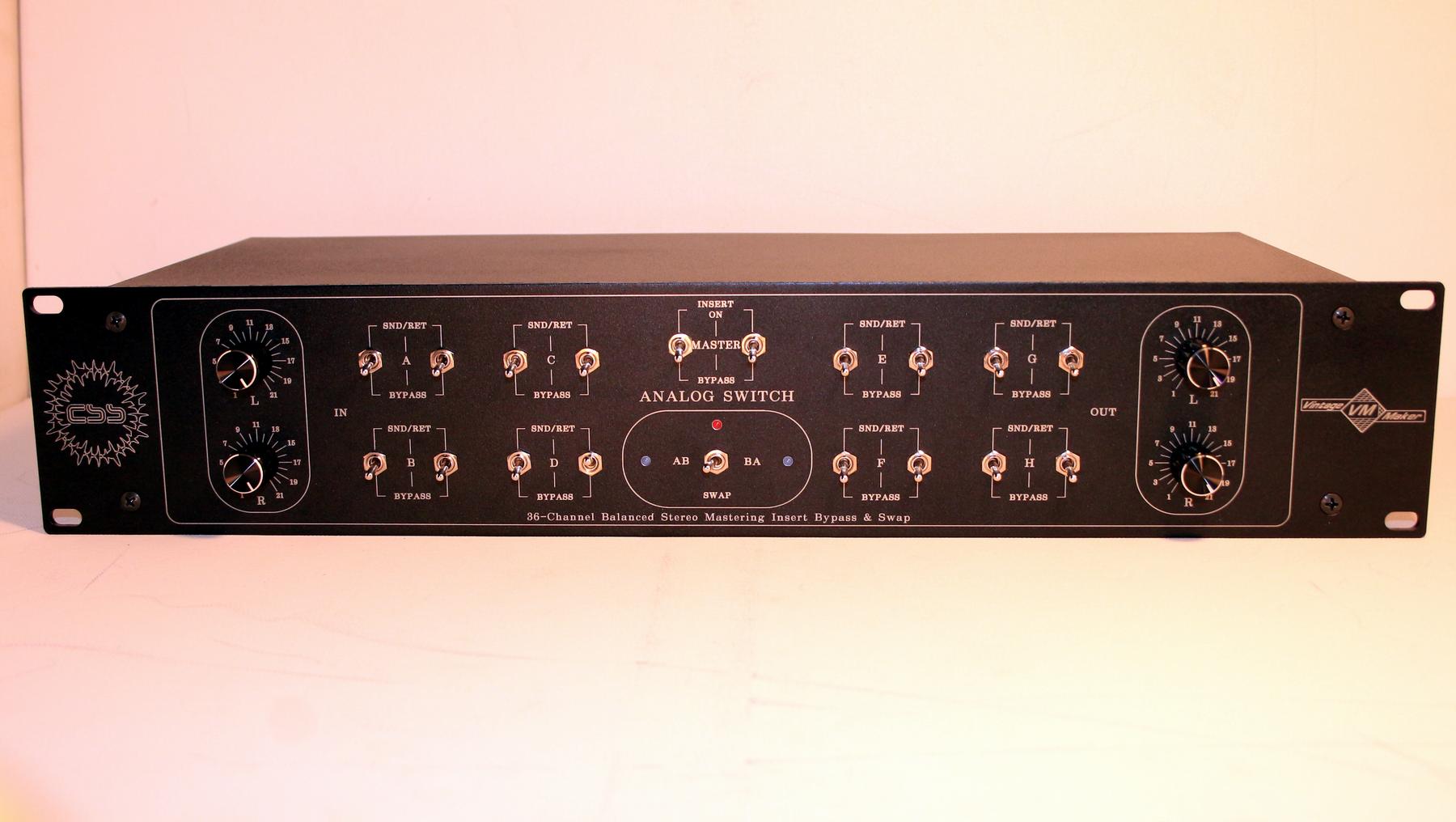
A professional 8-Stereo channel stereo mastering insert switcher designed for mastering studios, analog outboard processing, hybrid mixing and critical A/B comparison.
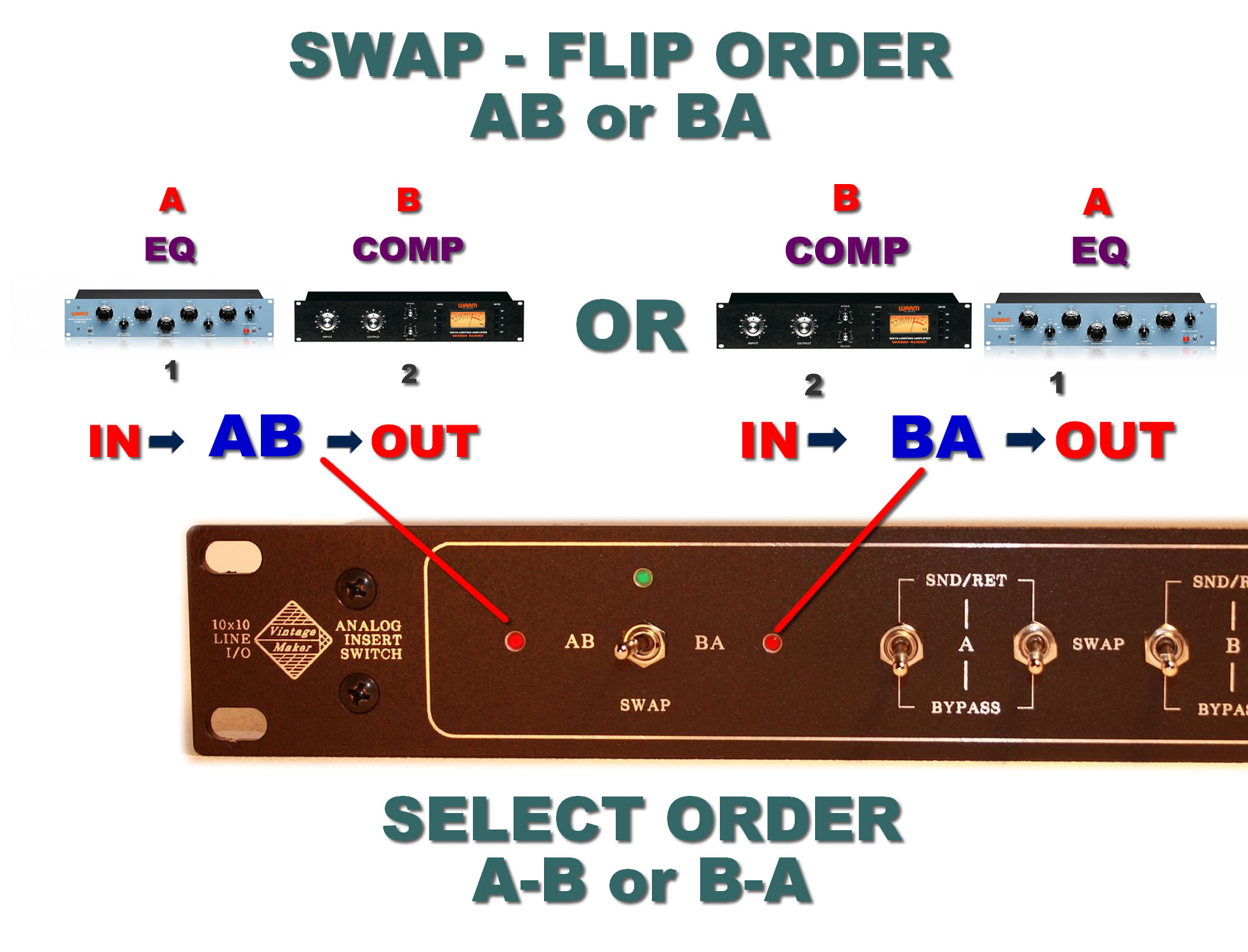
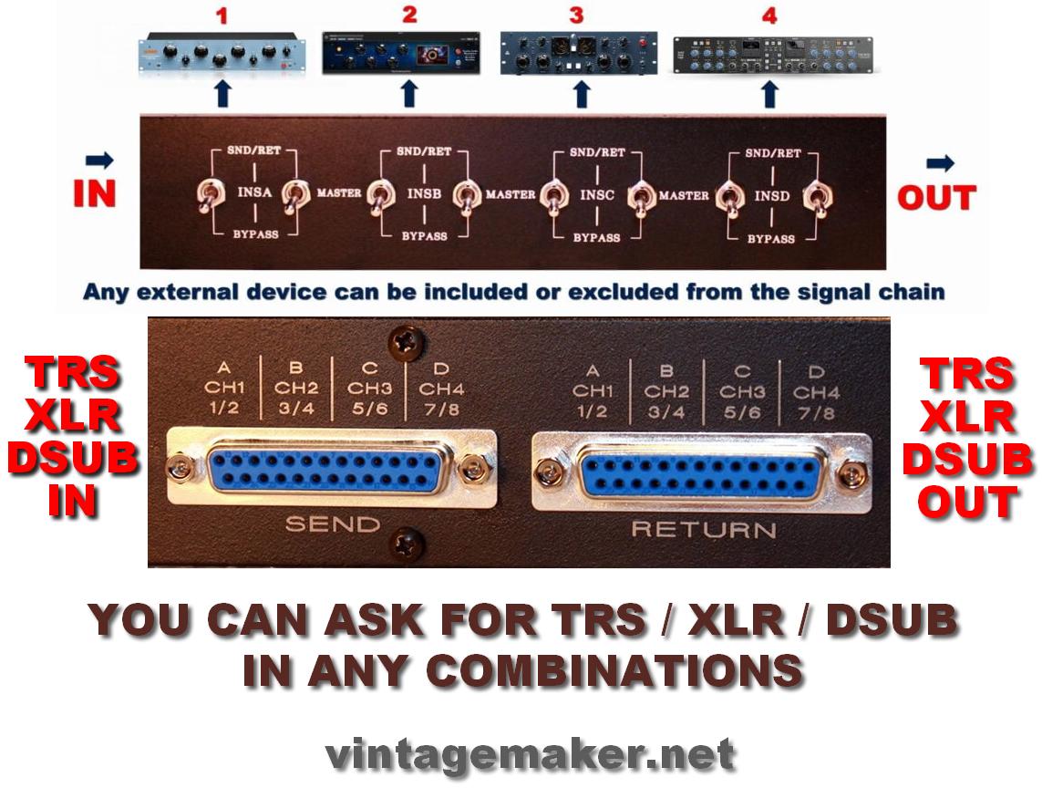
Connect up to 8 stereo outboard processors and switch each stereo insert independently between SEND/RETURN and BYPASS, without repatching cables. The unit also provides adjacent insert flip/swap switching, allowing the order of neighboring outboard processors to be reversed — for example A/B → B/A, B/C → C/B, C/D → D/C, and so on.
How the Signal Path Works
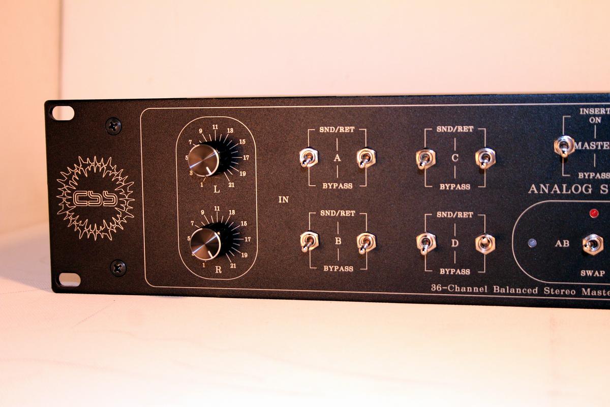
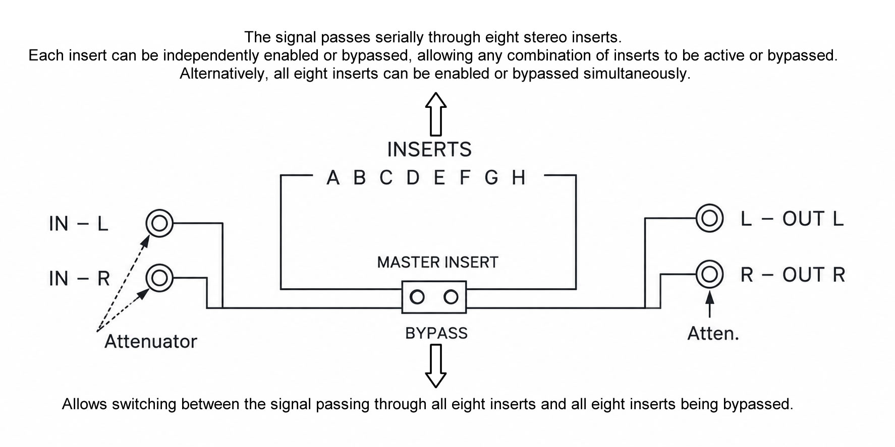
The audio signal first reaches the Input Attenuator, which provides precise L/R input level control, and then passes serially through all 8 stereo insert positions (A–H).
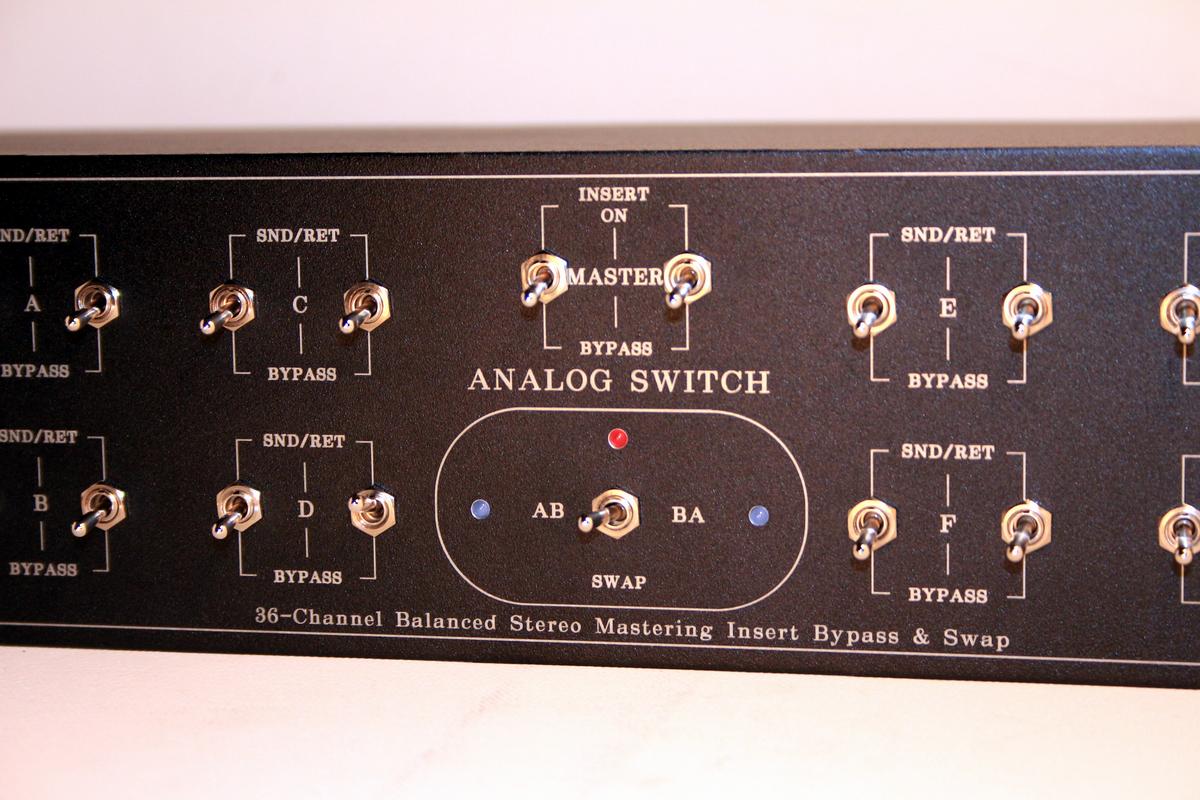
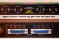
Each insert can be bypassed individually, or all 8 inserts can be bypassed simultaneously using the Master Insert Bypass switch.
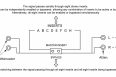
The selected outboard processors are therefore connected in series, allowing you to create a complete mastering chain. The processing order of two adjacent inserts can also be reversed — for example AB/BA, or BC/CB, or CD/DC, and so on — using the adjacent Flip/Swap function. After passing through the insert section, the signal reaches the Output Attenuator, which provides precise L/R output level control for final level matching. The swap configuration is fully customizable when ordering.
8 Stereo Insert Paths
- 8 x stereo insert paths – A to H
- Each stereo insert uses 2 stereo switches: 1 × SEND + 1 × RETURN, providing maximum signal isolation.
16 stereo switches total. - Independent bypass control for every insert
- Passive analog signal switching
- Ideal for mastering EQs, compressors, limiters, saturators and other stereo outboard processors
Flip / Swap Function
The adjacent outboard positions can be swapped to change their processing order. Examples:
A/B → B/A
B/C → C/B
C/D → D/C
D/E → E/D
E/F → F/E
F/G → G/F
G/H → H/G
Only adjacent inserts can be swapped.
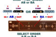
The exact swap sequence can be specified when ordering. For example, you can request AB/BA, BC/CB, CD/DC, or another adjacent sequence. This makes the unit particularly useful for mastering workflows where two processors need to be compared in different processing orders without physically repatching the system.
Balanced Studio Connectivity
Main input and output connections can be specified as:
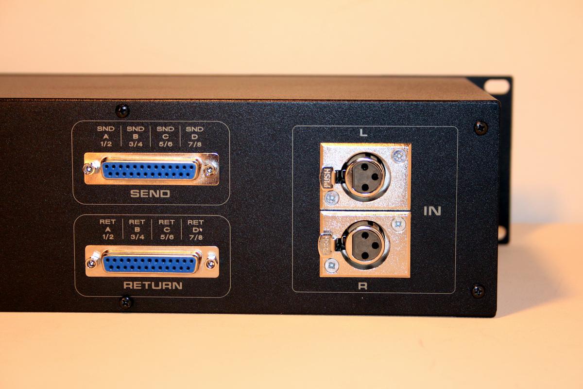
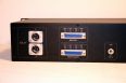
- 2 x stereo balanced inputs – TRS or XLR (choose your preferred configuration)
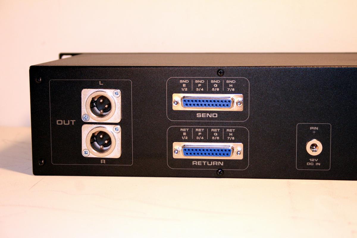
- 2 x stereo balanced outputs – TRS or XLR (choose your preferred configuration)
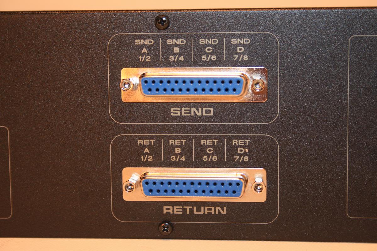
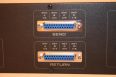
- 8 x stereo insert SEND via balanced DSUB
- 8 x stereo insert RETURN via balanced DSUB
The DSUB connector layout can also be customized to suit your preferred configuration – see more…..
Connector configuration can be customized to your studio setup.
Precision Attenuation
Optional precision stepped attenuation is available on both input and output:
21-Step Precision INPUT Attenuator
- L/R independently adjustable for precise stereo level matching
- 0 to -30 dB
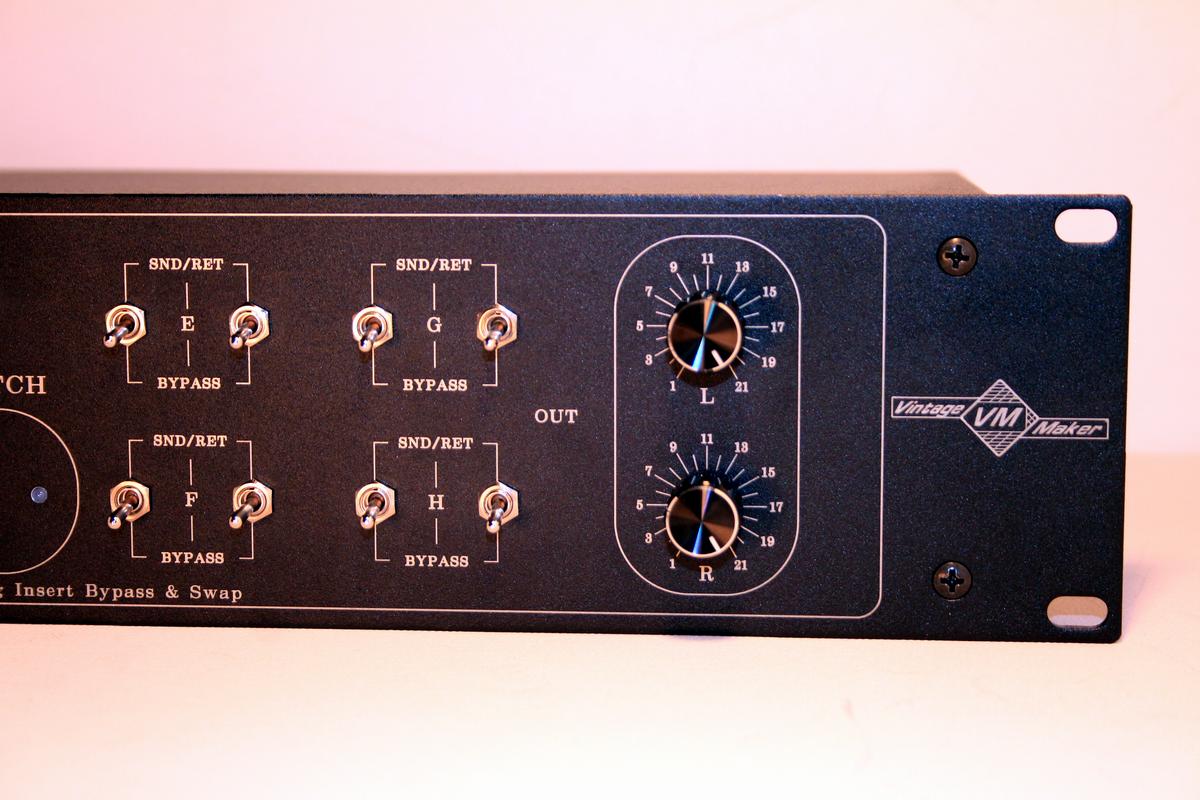
21-Step Precision OUTPUT Attenuator
- L/R independently adjustable for precise stereo level matching
- 0 to -26 dB
This allows precise level matching when comparing different mastering chains or integrating equipment with different operating levels.
Master Insert / Bypass
A dedicated Master INSERT / BYPASS switch allows the complete external insert chain to be bypassed. This provides a fast way to compare:
Direct signal ↔ Complete mastering insert chain without changing the individual processor settings.
Technical Specifications
- Format: 2U standard 19″ rack
- Architecture: Passive analog signal switching
- Stereo inserts: 8
- Insert positions: A–H
- SEND switches: 8 stereo
- RETURN switches: 8 stereo
- Total insert bypass switches: 16 stereo
- Main I/O: Balanced TRS or XLR, selectable/custom
- Insert I/O: Balanced DSUB
- Input attenuation: 21-step, 0 to -30 dB
- Output attenuation: 21-step, 0 to -26 dB
- Master Insert/Bypass: Yes
- Flip/Swap: Configurable adjacent insert pairs
- Frequency response: +0 / -0.1 dB, 10 Hz – 30 kHz
- Maximum level: > +28 dBu
- Noise floor: < -94.5 dBu, 22 Hz – 22 kHz bandwidth
- THD+N: < 0.004%
- IMD: < 0.004%
- Crosstalk rejection: > 110 dB (passive section)
Custom Configuration
This is a custom-build studio switching device. You can specify:
- TRS or XLR main I/O
- Desired connector configuration
- Flip/swap sequence
- LED colour for swap indication
- LED colour for power indication
- Custom front-panel name engraving
- Other configuration requirements
The order of the outboard processors can be swapped — AB/BA, BC/CB, CD/DC, etc. Let me know your required sequence when ordering.
Built for Your Studio
If you need a different number of channels, connectors, attenuation ranges, switching functions or routing options, I can build the unit to your exact requirements.
Do not find your desired configuration? Ask me to build yours. You can get as many channels and options as required — let’s build your gear.
KEY FEATURES
- 8 x Stereo Mastering Insert Paths
- 8 x Stereo SEND / RETURN
- 16 x Stereo Insert Bypass Switches
- A–H Insert Labelling
- Passive Analog Signal Switching
- Adjacent AB/BA Flip-Swap Function
- Custom Swap Sequence
- 2U Standard 19″ Rack Format
- Balanced TRS or XLR Main I/O
- Balanced DSUB Insert I/O
- 21-Step Input Attenuator: 0 to -30 dB
- 21-Step Output Attenuator: 0 to -26 dB
- Master Insert / Bypass Switch +28 dBu Maximum Level
- < -94.5 dBu Noise Floor
- < 0.004% THD+N
- 110 dB Crosstalk Rejection
- Custom LED Colours
- Custom Name Engraving Available
- Custom Routing Available
Technical Note: Passive Attenuator Interaction
This interaction only applies when both the Input and Output attenuators are selected.
If only the Input attenuator or only the Output attenuator is selected, there is no interaction between two passive attenuator networks, and the independently measured Step/dB values remain valid.Attenuation per step, measured independently with a balanced signal:
Step 1 = 0 dB
Step 2 = −2.5 dB
Step 3 = −4.4 dB
Step 4 = −7.0 dB
…and so on
— see the full Step/dB attenuation diagram: https://vintagemaker.net/documentation/#21-step-precision-vol-control-mono-input-1
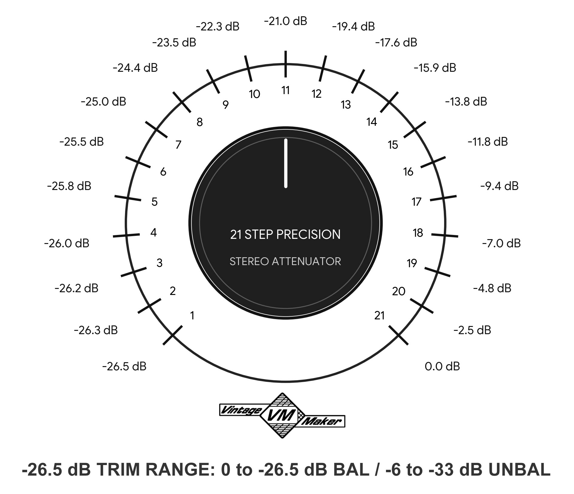
When both Input and Output attenuators are selected, and no outboard equipment is connected or the Master Insert is bypassed, the two passive attenuator networks are directly connected and therefore load each other. As a result, the original independently measured Step/dB values change due to the impedance interaction between the two attenuators.
The Output attenuator remains:
0 / −2.5 / −4.4 / −7.0 dB
while the Input attenuator measures:
0 / −4.0 / −6.7 / −9.0 dB
This is a normal characteristic of a fully passive, unbuffered signal path, caused by the impedance interaction between the two attenuator networks. It is not a fault or malfunction; it is a normal operating characteristic of the passive design.
Do not find your desired gear? Ask to build Yours!
You can get as many channels and options as you want, so let’s build your gear!
Build time: 18 Working Weekdays after cleared payment
| IN-OUT CONNECTION TYPE | TRS IN – TRS OUT, XLR IN – XLR OUT |
|---|---|
| INSERT SWAP SEQUENCE | AB/BA, BC/CB, CD/DC, DE/ED, EF/FE, FG/GF, GH/HG |
| PRECISION I/O ATTENUATOR L/R | NONE, INPUT, OUTPUT, BOTH |
| POWER LED COLOR | WHITE, RED, GREEN, YELLOW, BLUE |
| SWAP LED COLOR | WHITE, RED, GREEN, YELLOW, BLUE |
| CUSTOM NAME? | YES (let me know), NO THANKS |
| BUILD TIME | 18 WORKING DAYS |
Be the first to review “8 x Stereo Mastering Insert Bypass & Flip-Swap – I/O Precision Attenuator”
You must be logged in to post a review.
You may also like…
-
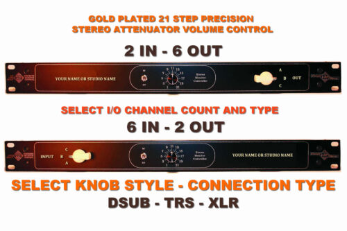
2×6 or 6×2 Monitor Controller Master Mono – DSUB-TRS-XLR (select connection)
Price range: 309.00 € through 353.00 € -
-

-
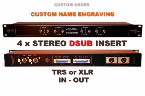
4 x Stereo DSUB Mastering Insert Bypass studio switch – TRS or XLR I/O (select)
Price range: 495.00 € through 515.00 € -
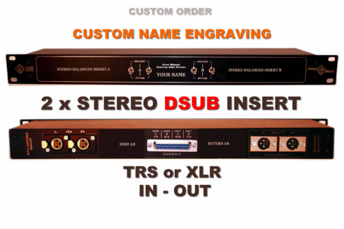
2 x Stereo DSUB Mastering Insert Bypass-TRS or XLR I/O (select)
Price range: 355.00 € through 375.00 € -
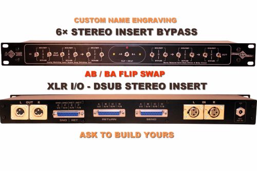
6 x Stereo Insert Bypass Studio Mastering switch Flip – Swap relay switcher box
Price range: 835.00 € through 855.00 € -
-
Related products
-

-
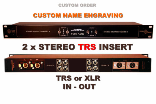
2 x Stereo TRS Mastering Insert Bypass studio switch – TRS or XLR I/O (select)
Price range: 395.00 € through 415.00 € -
Sale!
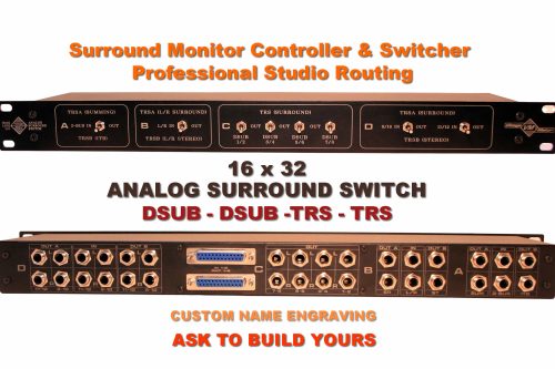
Surround Studio Monitor Switcher | Analog Routing Control
Original price was: 799.00 €.699.00 €Current price is: 699.00 €. -
Sale!
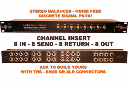
8-In 8-Out TRS – Channel Insert Studio Switch – Patchbay Instrument Effect Signal Switcher – Replace Your Patchbay for Clean, Fast Routing
Original price was: 650.00 €.589.00 €Current price is: 589.00 €.
Reviews
There are no reviews yet.